MEASURING INSTRUMENTS
Mass Production which is the foundation of modern industry is based on measured and interchangeable parts. That is to say that mass production is impossible if component parts could not be produced to close dimensional tolerances and thus made interchangeable.
The measuring instruments can be classified into;
(A) DIRECT MEASURING INSTRUMENTS: In direct measuring instruments, The dimension is determined directly. (e.g) Micrometer, Vernier Caliper, Vernier Height Gauge, Bevel Protractor etc. Such Instruments are simple and most widely used in production.
(B) INDIRECT MEASURING INSTRUMENTS: In indirect measuring instruments, The dimensions are determined by measuring other values functionally related to the required value.
E.g Dividers, Caliper, Sine Bar, Sine Center etc.
Below are the most best used measuring instruments you must have in a workshop.
(1) CALIPERS: Calipers are used to pick off dimension or distance from a workpiece. This setting is then measured with a scale, vernier caliper or micrometer. There is no provision for reading the caliper directly. That is why it is grouped as indirect measuring instrument. Calipers are designed as:
Outside Caliper, Inside Calipers and Odd leg or Hermaphrodite Calipers.
(i) The Inside caliper measures holes or inside dimensions
(ii) The Outside caliper measures thickness and outside dimensions.
(iii) Hermaphrodite caliper have one leg bent and the other leg equipped with scriber. Distances from the edge of a workpiece may be scribed or measured with this caliper.
(iv) Dividers: The dividers look like calipers, except that they are equipped with two scribers. They are used for taking accurate measurements or scribing of Arcs. They are used mainly for the layout of a workpiece.
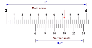
A second jaw is mounted upon the beam and can be moved along it. This sliding jaw has a clamp screw and its frame is marked by a vernier scale. The component or thickness to be measured is placed between the jaws of the caliper and the sliding jaw closed up to obtain a correct feel. The sliding jaw is then clamped to the beam and the caliper removed for reading.
NOTE: When the zero on the vernier scale coincides with the zero on the main scale, the number of divisions on the vernier scale is one more or less than the number of division on the main scale with which it coincides exactly.
In metric systems, there are two variations of vernier scale:
(i) Where the main scale is graduated into 1 mm and 0.5 mm.
(2) MICROMETER SCREW GAUGE: The Principle of micrometer consists of the employment of a screw and a nut, both having accurately cut thread. One complete revolution of the screw will advance it in relation to the nut threads, A distance equal to the lead of the thread. The parts of a micrometer includes;
(i) a U - Shaped Frame
(ii) The Barrel or Sleeve
(iii) The Thimble
(iv) The Spindle
(v) The Anvil
(v) The Ratchet etc.
The linear/main scale of the micrometer graduated in mm is engraved on the barrel (sleeve), While the vernier/circular scale with 50 divisions is engraved on the bevelled surface of the thimble. The spindle is rotated by the Thimble. The spindle thread has a pitch of 0.5 mm. One complete turn of the spindle therefore moves the spindle through a distance of 0.5 mm. Since the thimble has 50 equal divisions, It then implies that turning through one divisions. Therefore moves the spindle through 0.5/50 =0.01 mm.
This is the accuracy of reading the micrometer, on the smallest dimension which the micrometer can measure.
(3) SLIP GAUGES: Slip Gauges are the practical standard of length for use in the workshop where a tolerance as low as 0.001 mm is needed. These are rectangular blocks of steed having a cross - section of about 32 mm and 9 mm.
These gauges before being finished to size, are hardened and carefully matured so that they are independent of any subsequent variation in shape or size. After being hardened, The blocks are carefully finished on their measuring faces to such a fine degree of finish, flatness and accuracy that any two such faces when perfectly clean may be wrong together. This is accomplished by pressing the faces into contact and then imparting a small twisting or sliding motion while maintaining the contact pressure. When two gauges are wrong, together they adhere so that considerable force is needed to separate them and the overall dimension of a pile made of two or more blocks so joined is exactly the sum of the constituent gauges. Gauge blocks are available in sets with steps of 10, 1, 0.1, and 0.001 mm.
On small size blocks, the size is marked on the measuring face, and large blocks are marked on a side surface. Slip gauges are available in sets of 46 pieces, 110 pieces etc.
SIZE INCREMENT NO. OF PRICES
1.001 to 1.009 0.001 9
1.01 to 1.49 0.01 49
1.50 to 24.50 0.50 48
25 to 100 25.00 4
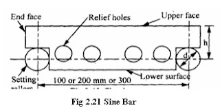
(4) SINE BAR: Under shop conditions, the sine bar is the most accurate straight bar in which two accurately lapped cylindrical plugs are located with extreme precision. There are two common types of sine bar designs.
 |
| Fig (a) |
 |
| Fig (b) |
In design (a) as shown above in fig (a), The ends of the bar are stepped and the plugs are secured into each step by screw.
In design (b), The plugs project about 12 mm from the front face of the bar. The center to center distance of the plugs is 100, 200, 250, or 300 mm.
The following conditions must be satisfied to close tolerance;
(1) The diameter of the plugs must be the same.
(2) The center distance between the plugs must be absolutely correct, and the centerlines of the two plugs must be parallel.
(3) One surface (The Measuring Surface) of the sine bar must be absolutely parralel to the center line of the plugs.
The sine bar is always used in conjunction with a true surface (surface plate). The angle to be measured is determined by an indirect method, as a function of sine. For this reason, the device is called the sine bar.
PLEASE DON'T FORGET TO SHARE, COMMENT, FOLLOW US, LIKE MY FACEBOOK PAGE, AND SUBSCRIBE TO GET THE LATEST UPDATES..


