When life gives you more than you can stand - KNEEL!!!

A man who works with his hands is a labourer; A man who works with his hands and his brain is a craftman; but a man who works with his hands, his brain and his heart is an artist (Louis Nizer) - woodworkinglearnerbasics.blogspot.com

YOU ARE CAPABLE OF MORE THAN YOU KNOW...

Woodworking is a most satisfying pastime, So varified and multifaceted you will never complete the twin processes you have undertaken: Acquiring tools and learning how to use them. You have begun a lifetime pursuit. (Michael Dunbar) - woodworkinglearnerbasics.blogspot.com

THE SECRET TO HAVING IT ALL... IS BELIEVING YOU ALREADY DO...

Ultimately, Literature is nothing but carpentry... Both are very hardwork. Writing something is almost as hard as making a table. With both you are working with reality, a material just as hard as wood. Both are full of tricks and techniques. Basically very little magic and a lot of hardwork. (Gabriel Garcia Marquez) - woodworkinglearnerbasics.blogspot.com

Live The Life You Only Imagined - BELEIVE

The feel and beauty of finely crafted wood... The refreshing smell of your workshop... The absorbing joy of cutting and joining that makes the hours race by... These are the reasons you love woodworking.. (Jack Neff) - woodworkinglearnerbasics.blogspot.com

Do What You Love and Do It Often - DESIGN YOUR OWN WOODWORKS TODAY - You Got This!!!

Welcome to my Blog about the fundamental Learner basics of WoodWorking, Wood, Carpentry, Craftmen, Tools, Workshops, WoodWorkers and the like. It has been my pleasure digging through lots of old books and doing my researches to find all these solutions to your questions... ENJOY!!... (ONUOHA MIRACLE) - woodworkinglearnerbasics.blogspot.com

Sunday, June 17, 2018

POWER HACKSAW


THE MECHANISM OF POWER HACKSAWS


Power Hacksaws are usually of simple construction whose cutting action is brought about the reciprocating motion of the saw blade. It consists essentially of a drive unit, crank mechanism, slide, feed weight, a clamping unit and a frame which carries all the above units.

 An electric motor is the source of power, mounted at the bottom to one side of the frame, The crank is a disk which carries a slot or a set of holes onto which the link is attached. The link actuates the slide onto which the saw blade is clamped. The slide has an inverted U shape on top of which there is a feed weight. The feed weight is fixed in position by a link attached to the upper part of the machine frame. By moving the feed weight along the link, the weight acting on the saw blade can be varied. The greater the weight acting at the saw blade, the higher the feed rate, That is, the lesser time it takes to cut the work-piece.

 The Crank is driven by the electric motor through vee-belts and a pulley only, or in conjunction with a pinion and wheel drive. The work-piece is clamped in a machine vice with opposed - travel jaws. The stroke of the slide is adjusted by adjusting the crank pin on the crank slot. The slot gives a step less stroke adjustment.

 In some designs, two, three, or four holes are used for step - wise stroke adjustments. The power hacksaw is usually of a cast construction with the major component made from castings, However, Power hacksaws of welded construction exists for one - off or low piece production. The capacity of power hacksaws are given  by the maximum size of work that can be sawn. Usual capacities range from 75 x 75mm square or round stock for a large machine.

 Most power hacksaws have facility for the cutting off of repetitive parts which consists of a long - rod, with a stopper at one end. The rod can be adjusted such that the distance between the stopper and the fixed saw blade can be varied to suit the length to be cut. Most power hacksaws have circulating coolant system.

It should be noted that when sawing generally, It is faster to cut through a smaller thickness than through a larger one.
For Example; It is faster to cut the 25mm thickness on a solid bar of 25 x 50mm, than through the 50mm thickness.

 The tooth profiles of power hacksaw, blades are similar to those of hand hacksaw except that the former and bigger and sturdier.
 Blade materials are usually carbon tool steels and high speed steels. Carbon steel blades are cheaper but have low life due to frequent breakage and high tooth wear. Due to unavailability of tool materials in Nigeria, Both hand and power hacksaw blades have been made from leaf springs, scrap saw mill blades and mild steel strips ( which were case hardened ).
Power saw blades come in different sizes and pitches. Some particular sizes are L x W x T x N = 350 x 25 x 1.25 x 14 teeth and 400 x 32 x 1.60 x 10 teeth, Where L, W and T are the length, width and thickness  of the blade in (mm) respectively and n is the number of teeth per 25mm length of blade.

Saturday, January 13, 2018

FEATURES OF A TYPICAL DRILLING MACHINES


 The Drilling Machine is used for producing holes in work pieces. It is a very important machine tool which is commonly used in the workshop. The holes made may be through or blind. The common tool used in the machine is the "TWIST DRILL". The holes produced may be finished or modified by Boring, Reaming, Counterboring, Tapping or Spot Facing.

 This machine is made up of essentially the base, column, spindle, table, fixed head and the adjustable head or sleeve. The base, carries the whole drilling machine structure. It is a casting with slots for bolting the machine to the floor or to a pedestal. The column supports the drill press head and also the table on some machines. The columns are usually circular in section. The fixed head carries the sleeve, spindle, and feed gears. The spindle carries the drill or other cutting tools and resolves in a fixed position in the sleeve.

 The sleeve which does not resolve carries the spindle, But may slide in it's bearing in a direction parallel to it's vertical axis. The spindle is usually vertical and work is supportable on a horizontal table.

 The table is supported on an arm which is adjustable on the lower section of the column. The table is adjustable vertically to accommodate different heights of work It may be swung out of the way so that the work can be seated on the base if required. The common drilling machines maybe of the pedestal type which maybe mounted on any suitable support and are usually of small capacities and the pillar type which are usually mounted directly on the floor. The sizes of these machines are usually given in terms of the maximum diameter of holes that can be drilled with the twist drill. The size may also be expressed as a maximum distance from the center of the spindle to the nearest point on the column of the machine. For example; A drilling machine with work capacity of 400 mm diameter is called a 400 mm Drilling Machine.

Friday, January 12, 2018

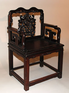
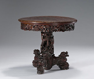
The Art Of Chinese Wood Carving And Furniture.

 The Art Of Chinese Wood Carving And Furniture.

    Wood Carving is a sculpture in Chinese culture often knows referred to as "FOLK ART". Wood carving is a separate type of work out of the woodwork. It is divided into three categories: "Three dimensional carvings", "Root carving", "Relief sculpture". Wood carving uses several techniques including circular engraving, basso-relievo and hollow engraving. Most wood carving applies color to protect the wood. The form of Chinese furniture evolved along three distinct lineages which dates back to 1000 BC, based on frame and panel, yoke and rack and bamboo construction techniques. Chinese home furniture evolved independently of Western furniture into similar forms including chairs, tables, stools, cupboard, cabinets, beds, and sofas. Until the 10th century CE the Chinese sat on mats or low platforms using low tables, in typical Asian style, but then gradually moved to using high tables with chairs.

Chinese Wood Carving And Furniture.

Chinese Wood Carving And Furniture.
   

       Chinese furniture is mostly in plain polished wood, but from at least the Song Dynasty, the most luxurious pieces often used LACQUER to cover the whole or parts of the visible area. Carved lacquer furniture was at first only affordable by the Imperial family or the extremely rich, but by the 19th century was merely very expensive, and mostly found in smaller pieces or as decorated area on larger ones.

Chinese Wood Carving And Furniture.
     
Chinese Wood Carving And Furniture.

     Chinese Furniture is usually light where possible, from the Qing Dynasty furniture made for export, mostly to Europe, became a distinct style, generally made in rather different shapes to suit the destination markets and highly decorated in lacquer and other techniques.

Chinese Wood Carving And Furniture.Chinese Wood Carving And Furniture.
     
  
Classic furniture is typically made of a class of hardwood, known collectively as ROSE WOOD. These woods are denser than water, fine grained and high in oils and resins. These properties make dimensionally stable, hardwearing, hot and insect resistant.

Chinese Wood Carving And Furniture.
Chinese Wood Carving And Furniture.   


  Many basic patterns established during the song dynasties continued to mature throughout the Yuan and Ming periods into beautiful well-rounded and robust forms that were smoothly finished with thick lacquer coating and finely detailed with painted decoration.

Chinese Wood Carving And Furniture.


Chinese furniture began to develop some of its distinguishing characteristics:
  • The use of meditation Chairs, large enough to sit cross legged in.
  • Tall yoke chairs where the feet are to rest on a bottom stretcher day beds.
  • Opium beds where one can sit cross legged and use small tables to eat from or write on      while sitting on a mat or platform.
  • Use of thick lacquer finish 
  • Exotic hardwoods
  • Detailed engraving and paintings for ceremonial purposes and artistic expression sacred mountain images, Dragon and Clouds, birds and flower all had specific Taoist connotation.
Chinese Wood Carving And Furniture.Chinese Wood Carving And Furniture.


PLEASE DON'T FORGET TO SHARE, COMMENT, FOLLOW US, LIKE MY FACEBOOK PAGE, AND SUBSCRIBE TO GET THE LATEST UPDATES..

Top 5 Most Important WoodWorking Tool You Must Have In Every Workshop.

(1) THE LAYOUT SQUARE


 The Layout Square tool also know as a speed square is a triangular shaped measuring tool usually available in 6-12 inch models, It can be used for scribing square 90 degrees cutting lines on pieces of woodworking stock or framing lumber. This tool can also be used to measure the angle on a board that is already cut. Note that the layout Squares can come in different models such as aluminium or plastic models. Choose the aluminium as they are practically indestructible. The plastic ones are a bit cheaper, but they won't last longer.

(2) THE NAIL SET


 The Nail Set is a tool used to drive finishing nails into furniture, Trims and Moulding. The nail set has a very distinctive shape that allows for easy use which comes right after you have nailed the nail in as far as it will go, Just until the point where the nail head is slightly above the material being used.
 In woodworking and construction, A nail is a pin shaped object made of metal which is used as a Fastener, Peg to hang something, or sometimes as a decoration.

(3) THE CLAW HAMMER


 The Claw Hammer is a tool primarily used for driving and extracting nail from and into objects. A claw hammer can be said to look like the letter "T" with the handle being the log part and the head being the line across the top which looks like a T. The claw hammer can be constructed in many ways but generally comes in two forms which are:

(i) The Single-Piece Heat-Treated Steel and
(ii) The Framing Hammer

(4) THE TAPE MEASURE


 The Tape Measure is a tool which has a narrow strip (as of a limp cloth or steel tape) marked off in units (Such as Inches or Centimeters) for measuring. It can also be seen as a flexible ruler, which consists of a ribbon cloth, plastic, fibre glass, or metal strip with linear measuring markings, It is a common measuring tool. Its design allows for a measuring of great length to be easily carried in pocket or toolkit and permits one to measure around curves or corners.

(5) SCREW DRIVER


 The Screw driver is a tool, Manual or Powered, for turning (driving or removing) screws. A screw driver is classified by its tip, which is shaped to fit the driving surface, slots, grooves, recesses etc. A typical simple screw driver has a handle and a shaft and a tip that the user inserts into the screw head to turn it. The shaft is usually made of tough steel to resist twisting or bending. Screw drivers come in a large range of sizes to accommodate various screw. The screw drivers consists of four parts which are;
(i) The Handle
(ii) The Shank
(iii) The Blade and;
(iv) The Tip.

The two most common screw driver tips are:

 (i) The Slot Head: The Slot Head screwdriver (Flat head/Regular screwdriver), is a screwdriver which consists of a single flat blade that fits in the single slot of traditional screws.


 (ii) The Phillips-Head Screwdriver: The Phillips-Head Screwdriver has a four star point at the end that fits into the corresponding Screw Shallow, Cross-Shaped Depression.
A wide variety of power screwdrivers range from a Simple Stick-Types with Batteries, A motor, and a Tip holder all in line, to powerful pistol type VSR (Variable - Speed Reversible) cordless drills that also functions as screwdrivers. A quality construction of vital to good set of screwdrivers. So many of them are made out of soft metal, and the first time you put any "Oomph" behind them, they strip out becoming absolutely useless.

TOP BEST PRECAUTIONS TO BE TAKEN TO GETTING THE MOST OUT OF WELDING.

WELDING PRECAUTIONS

 In common with other operations involved in the workshop, Welding creates hazards which if not identified, constitutes a threat to safety of both the welder and other workers in the vicinity. Some precautions observed during welding include:

(i)  Correct protective clothing must be worn (Apron, Hand Gloves etc).
(ii) Safety boots with hard sole should be worn to avoid being hurt when a hot metal is marched mistakenly.
(iii) Ensure adequate ventilation.

ARC WELDING


(iv) Welding mask should be worn to avoid arc - eye.
(v) Correct nose mask/respirator must be worn so that you don't inhale poisonous gases or fumes.
(vi) Ensure that the isolating switches are to hand so that the main supply can be disconnected as quick as possible.
(vii) Ensure that the equipment earth lead is securely fastened to a satisfactory earth point.
(viii) Ensure that the welding lead, Welding return and earth lead are of adequate size for the current being used.
(ix) Effort should be made to avoid welding in damp or wet conditions, Since the danger from electric shock is much increased etc.

GAS WELDING


(x) Never use a naked flame to find a suspected leak, Use a brush to apply a soapy water to any joint suspected of leaking. Bubbles will appear if there is a leak.
(xi) Check regulators, hoses and blowpipes at frequent intervals, discard any damaged equipment.
(xii) Do not allow oil or grease to get on cylinder. Oxygen reacts violently with oil and grease and may explode.
(xiii) When the equipment is not in use, or when the cylinder is empty, close the cylinder valves.
(xiv) Always open the cylinder valves slowly.
(xv) Do not leave the blowpipe near hot metal or any escaping acetylene gas may be ignited etc.
                                                                                                                                         

Monday, January 8, 2018

TOP TIPS TO SAVING A VICTIM OF AN ELECTRIC SHOCK IN A WORKSHOP


ELECTRIC SHOCK

The surest way to avoid electric is never to work with live electrical equipment. No matter how many precautions are taken, There will still be people who suffer a shock. If this happens to someone else while you are near, Some rapid actions are needed to save the victim's life;

READ MORE: INDUSTRIAL/WORKSHOP SAFETY AND ACCIDENT PREVENTION

(i) The current should be switched off immediately if it is possible.
(ii) Never attempt to move a person who is in contact with a high voltage electric current above 650 volts.

(iii) When attempting to release someone still in contact with lower voltages, (E.g) 240V, Do not touch the person directly on the skin because you may receive a shock as well. Pull the person free with something dry and non conducting such as Rubber Gloves, Dry Wood, or Clothing.

(iv) Avoid using portable electric tools while standing on wet floors. If this must be done, wear thick rubber boots.

(v) Always switch off at the socket before filling plug. See that the machine switch is off before switching on the socket.

READ MORE: SOURCES OF ACCIDENTS


PLEASE DON'T FORGET TO SHARE, COMMENT, FOLLOW US, LIKE MY FACEBOOK PAGE, AND SUBSCRIBE TO GET THE LATEST UPDATES..

SOURCES OF ACCIDENTS


Accident is invariably preceded by an unsafe act or unsafe condition. or in some cases say the both. That is to say that the accident that occur in the workshop or factory can broadly be classified into Unsafe Acts and Unsafe Conditions.

READ MORE: TOP TIPS TO SAVING A VICTIM OF AN ELECTRIC SHOCK IN A WORKSHOP

(A) UNSAFE ACTS
Unsafe Acts are those acts/behaviors of workers which can lead to accidents. They may be negligence to instructions. Accidents caused by unsafe acts are those accidents which might have been prevented by his own precautions.
Unsafe acts that lead to accidents in the workshop include:
(i) Working without authority or permissions
(ii) Operating at unsafe speed.
(iii) Making safety devices inoperative.
(iv) Using unsafe equipment, hands instead of equipment or using equipment unsafely.
(v) Taking unsafe position.
(vi) Working on moving or dangerous equipment's.
(vii) Distracting, Teasing, Abusing, Startling etc.
(viii) Failure to use safe dresses or personal protective devices.


(B) UNSAFE (Mechanical or Physical) CONDITIONS
Unsafe conditions are those operating conditions which lead to accidents. Accidents caused by unsafe conditions are not the fault of the workers. They may be as a result of faulty designs or construction of machine, Building, Operating Practices, Lack of Standardization, etc.
The unsafe mechanical or physical conditions that can lead to accident include:
(i) Inadequately Guarded.
(ii) Unguarded
(iii) Defective Condition ( Rough, Sharp, Slippery, Decayed, Corroded, Cracked, etc.)
(iv) Unsafe Design or Construction.
(v) Inadequate or Unsuitable Illumination.
(vi) Inadequate or Improper Ventilation.
(vii) Unsafe Dress or Apparel.

(viii) Unsafe Method, Process, Planning etc.


PLEASE DON'T FORGET TO SHARE, COMMENT, FOLLOW US, LIKE MY FACEBOOK PAGE, AND SUBSCRIBE TO GET THE LATEST UPDATES..

INDUSTRIAL/WORKSHOP SAFETY AND ACCIDENT PREVENTION


Industrial/Workshop safety is defined as a situation which is free from danger or risks. Accident is defined as an unplanned, not necessarily injurious or damaging event which interrupts the completion of an activity. When accident occurs in a factory or workshop, damage may be done on either man, material or machine, or any combination of these three.

READ MORE: TOP TIPS TO SAVING A VICTIM OF AN ELECTRIC SHOCK IN A WORKSHOP

Everyday, a large number of accidents occurs in our factories. These sometimes results in death, sometimes in permanent disablement and in many cases, Fortunately, in nothing worse than a few days or weeks absence from work. Even if an accident does not render the victim unfit for work, It makes him liable to infections or any other of the ills which may be contracted as a result of injury and shock.

READ MORE: SOURCES OF ACCIDENTS

It has been observed that a lot of accidents occurs because of lack of safety awareness. Men fall from ladders, Operate their machines without a guard, Drop objects on their toes and cut their hands because of the misuse of tools. In every three accidents which occurs, two are caused by the personal element of the victim, and one by means beyond his control.

To put it briefly, We may say the two out of three are the victims own fault and the third was his employer's fault for not making safe working conditions.


PLEASE DON'T FORGET TO SHARE, COMMENT, FOLLOW US, LIKE MY FACEBOOK PAGE, AND SUBSCRIBE TO GET THE LATEST UPDATES..

BRIEF INTRODUCTION TO MARKING - OUT


BRIEF INTRODUCTION TO MARKING - OUT
Photo Credit: Stockillus
Before any work of cutting and shaping can be carried out to produce a component, The shape of the part and the position of holes and slots need to be drawn on the material, to be be a guide with which the filter can work.
This reproduction of engineering drawing on the material before commencing work is called "MARKING - OUT" and it must also be marked accurately.

READ MORE: TOP 7 PRECAUTIONS TO TAKE WHILE USING THE MARKING OUT TOOLS

 The first principle of any marking out is that all the lines must be measured from one vertical and one horizontal base line or datum. The lines are cut into the surface of the workpiece by the very hard and fine point of a scriber, chalk being used to make the line show more clearly. One line must be scribed and if this is to mark a hand or machine-cut edge, It must also be lightly center punched at intervals. The rough edge of the cut will obscure the line just as the final cut is due but the punch marks should show as a check on the accuracy of machining. Holes for drilling should be heavily punched at their centers, The circumference being lightly punched also.

Marking Out tools are of different various types which is well illustrated below.

READ MORE: TYPES OF MAKING - OUT TOOLS.


PLEASE DON'T FORGET TO SHARE, COMMENT, FOLLOW US, LIKE MY FACEBOOK PAGE, AND SUBSCRIBE TO GET THE LATEST UPDATES..

HOW TO USE THE MICROMETER


(1) Check the zero reading.

(2) Place the part to be measured in between the measuring faces.

(3) Advance the spindle by rotating the thimble until the measuring faces tough the part to be measured.

(4) Note the reading both on barrel scale and the circular scale of the thimble.

Reading = (Reading on barrel) + (0.01 x Reading of the thimble).


Sleeve Reading = 12.00
Thimble Reading = 0.01 x 8
Therefore, Anvil Gap = 12.00 + 0.08 = 12.08

Note; Inside Micrometers and Depth, Micrometers used to measure internal dimensions and depths respectively, works with the same principle of micrometer screw gauge.
The reading of these instruments are the same.


PLEASE DON'T FORGET TO SHARE, COMMENT, FOLLOW US, LIKE MY FACEBOOK PAGE, AND SUBSCRIBE TO GET THE LATEST UPDATES..

HOW TO READ A VERNIER CALIPER

Reading The Vernier Caliper

READING A VERNIER CALIPER
Photo Credit: Giphy.com
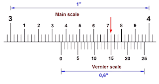
The main scale is read off up to the zero of the vernier scale. The vernier scale is read off at the division which coincides exactly with a main scale division.
This vernier scale reading is the number of 0.02 mm which must be added to the main scale reading.
So the number read off the vernier scale must be multiplied by 0.02.

Total reading = Opening of jaws of vernier caliper = Reading on main scale against zero mark on vernier scale + 0.02 x Mark number on vernier scale which coincides with a mark on main scale.

READING A VERNIER CALIPER
Photo Credit: Craftsmanspace
Reading = 22 + (0.02 x 16) = 22.32 mm

 It should be noted that vernier height gauges, vernier depth gauges used for measuring differences in height of two points and depth of holes respectively are similar to vernier caliper. The readings or scales of these other two instruments are the same as that of vernier caliper.


PLEASE DON'T FORGET TO SHARE, COMMENT, FOLLOW US, LIKE MY FACEBOOK PAGE, AND SUBSCRIBE TO GET THE LATEST UPDATES..

TOP 7 PRECAUTIONS TO TAKE WHILE USING THE MARKING OUT TOOLS


(1) Keep all marking - out tools clean and slightly oiled, and well away from all other tools.

(2) Take care to clean the tools and the work-piece before starting to mark out.

(3) Handle the tools carefully - no knocking or rubbing of the surface.

READ MORE: BRIEF INTRODUCTION TO MARKING OUT

(4) When transferring measurements from a rule, check that the point is fitted into the rule division accurately.

(5) Check that the clamps are tight on the scribing block.

(6) Center punch very lightly and exactly on the lines and line junctions.

(7) Always work from one vertical and one horizontal base line.


PLEASE DON'T FORGET TO SHARE, COMMENT, FOLLOW US, LIKE MY FACEBOOK PAGE, AND SUBSCRIBE TO GET THE LATEST UPDATES..

4 Most Best Used Measuring Instruments you must have in a workshop


                                         MEASURING INSTRUMENTS

Mass Production which is the foundation of modern industry is based on measured and interchangeable parts. That is to say that mass production is impossible if component parts could not be produced to close dimensional tolerances and thus made interchangeable.
If component parts should be produced to close dimensional tolerances, then measurements must be employed. In short measurement is used to control the dimensional accuracy of components being produced.

READ MORE: TOP BEST WAYS TO TAKE CARE OF YOUR MEASURING INSTRUMENTS.


The measuring instruments can be classified into;

(A) DIRECT MEASURING INSTRUMENTS: In direct measuring instruments, The dimension is determined directly. (e.g) Micrometer, Vernier Caliper, Vernier Height Gauge, Bevel Protractor etc. Such Instruments are simple and most widely used in production.

(B) INDIRECT MEASURING INSTRUMENTS: In indirect measuring instruments, The dimensions are determined by measuring other values functionally related to the required value.
E.g Dividers, Caliper, Sine Bar, Sine Center etc.
Below are the most best used measuring instruments you must have in a workshop.
(1) CALIPERS: Calipers are used to pick off dimension or distance from a workpiece. This setting is then measured with a scale, vernier caliper or micrometer. There is no provision for reading the caliper directly. That is why it is grouped as indirect measuring instrument. Calipers are designed as:
Outside Caliper, Inside Calipers and Odd leg or Hermaphrodite Calipers.
(i) The Inside caliper measures holes or inside dimensions 
(ii) The Outside caliper measures thickness and outside dimensions.
(iii) Hermaphrodite caliper have one leg bent and the other leg equipped with scriber. Distances from the edge of a workpiece may be scribed or measured with this caliper.
(iv) Dividers: The dividers look like calipers, except that they are equipped with two scribers. They are used for taking accurate measurements or scribing of Arcs. They are used mainly for the layout of  a workpiece.
(v) Vernier Calipers: The vernier caliper consists of a main beam of rectangular section with an integral fixed jaw. The beam is marked with a scale graduated into millimeter and half millimeters.

READ MORE: TOP 7 PRECAUTIONS TO TAKE WHILE USING THE MARKING OUT TOOLS

A second jaw is mounted upon the beam and can be moved along it. This sliding jaw has a clamp screw and its frame is marked by a vernier scale. The component or thickness to be measured is placed between the jaws of the caliper and the sliding jaw closed up to obtain a correct feel. The sliding jaw is then clamped to the beam and the caliper removed for reading.
NOTE: When the zero on the vernier scale coincides with the zero on the main scale, the number of divisions on the vernier scale is one more or less than the number of division on the main scale with which it coincides exactly.

In metric systems, there are two variations of vernier scale:
(i) Where the main scale is graduated into 1 mm and 0.5 mm.
(ii) Where the main scale is graduated in whole 1mm only.


READ MORE: TYPES OF MARKING OUT TOOLS AND THEIR USES.

(2) MICROMETER SCREW GAUGE: The Principle of micrometer consists of the employment of a screw and a nut, both having accurately cut thread. One complete revolution of the screw will advance it in relation to the nut threads, A distance equal to the lead of the thread. The parts of a micrometer includes;
(i) a U - Shaped Frame
(ii) The Barrel or Sleeve
(iii) The Thimble
(iv) The Spindle
(v) The Anvil
(v) The Ratchet etc.
  
The linear/main scale of the micrometer graduated in mm is engraved on the barrel (sleeve), While the vernier/circular scale with 50 divisions is engraved on the bevelled surface of the thimble. The spindle is rotated by the Thimble. The spindle thread has a pitch of 0.5 mm. One complete turn of the spindle therefore moves the spindle through a distance of 0.5 mm. Since the thimble has 50 equal divisions, It then implies that turning through one divisions. Therefore moves the spindle through 0.5/50 =0.01 mm.
This is the accuracy of reading the micrometer, on the smallest dimension which the micrometer can measure.
(3) SLIP GAUGES: Slip Gauges are the practical standard of length for use in the workshop where a tolerance as low as 0.001 mm is needed. These are rectangular blocks of steed having a cross - section of about 32 mm and 9 mm.
These gauges before being finished to size, are hardened and carefully matured so that they are independent of any subsequent variation in shape or size. After being hardened, The blocks are carefully finished on their measuring faces to such a fine degree of finish, flatness and accuracy that any two such faces when perfectly clean may be wrong together. This is accomplished by pressing the faces into contact and then imparting a small twisting or sliding motion while maintaining the contact pressure. When two gauges are wrong, together they adhere so that considerable force is needed to separate them and the overall dimension of a pile made of two or more blocks so joined is exactly the sum of the constituent gauges. Gauge blocks are available in sets with steps of 10, 1, 0.1, and 0.001 mm.
On small size blocks, the size is marked on the measuring face, and large blocks are marked on a side surface. Slip gauges are available in sets of 46 pieces, 110 pieces etc.
For example, A set of 110 pieces consists of the following sizes:

READ MORE: HOW TO USE THE MICROMETER

       SIZE                                     INCREMENT                              NO. OF PRICES

1.001 to 1.009                                      0.001                                                      9
   1.01 to 1.49                                          0.01                                                     49
 1.50 to 24.50                                        0.50                                                      48
     25 to 100                                          25.00                                                      4

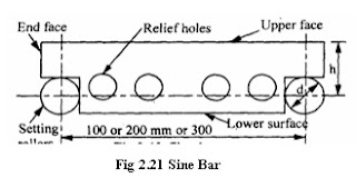
(4) SINE BAR: Under shop conditions, the sine bar is the most accurate straight bar in which two accurately lapped cylindrical plugs are located with extreme precision. There are two common types of sine bar designs.

SINE BAR
Fig (a)
SINE BAR
Fig (b)
In design (a) as shown above in fig (a), The ends of the bar are stepped and the plugs are secured into each step by screw.
In design (b), The plugs project about 12 mm from the front face of the bar. The center to center distance of the plugs is 100, 200, 250, or 300 mm. 

The following conditions must be satisfied to close tolerance;

(1) The diameter of the plugs must be the same.
(2) The center distance between the plugs must be absolutely correct, and the centerlines of the two plugs must be parallel.
(3) One surface (The Measuring Surface) of the sine bar must be absolutely parralel to the center line of the plugs.

The sine bar is always used in conjunction with a true surface (surface plate). The angle  to be measured is determined by an indirect method, as a function of sine. For this reason, the device is called the sine bar.

PLEASE DON'T FORGET TO SHARE, COMMENT, FOLLOW US, LIKE MY FACEBOOK PAGE, AND SUBSCRIBE TO GET THE LATEST UPDATES..

TYPES OF MARKING OUT TOOLS AND THEIR USES.


Below is a comprehensive list of marking out tools and their uses listed out and these marking-out tools include:

READ MORE: BRIEF INTRODUCTION TO MARKING OUT

(1) SURFACE PLATES
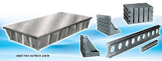
  This is a thick rigid and very flat plate which is used as the horizontal datum. It is made of cast iron and have very flat rectangular surface.

SURFACE PLATES

(2) ANGLE PLATES
  These are heavy and rigid, and the workpiece may be clamped finally to them on the surface plate. Angle plates are made from cast iron.

ANGLE PLATES

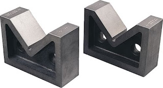
(3) VEE - BLOCKS
  Vee Blocks are supplied in pairs. They are rectangular with a vee-shaped recess in one side and are used on the surface plate to support cylindrical works. Vee Blocks are made of chilled cast iron.

VEE BLOCKS

(4) SCRIBERS
  The Scriber is a thin rod with very hard, fine pointed ends which is used to cut the lines in the surface of the workpiece. Scribers are made from hardened and tempered high carbon or cast steel.

SCRIBERS

(5) SCRIBING BLOCK
  The Scribing Block has an accurately machined flat base and a supporting pillar upon which is mounted a scriber with a hooked end. The scriber can be clamped at any desired position on the pillar, and then brought into contact with the work. 
Finally, the base of the scribing block is held firmly against the surface plate and moved slowly so that the scriber marks a line on the component. By raising or lowering the scriber point, lines parallel to the first can be marked on the work. Scribing Block is made from high carbon or cast steel.

SCRIBING BLOCK

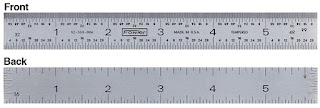
(6) STEEL RULE
  The rule is usually graduated in millimeters and inches measurements are picked from the steel rule.

STEEL RULE

(7) TRY SQUARE
   The Try Square is used with the feeler gauges to check the accuracy of right angled corners and with a scriber to mark out lines at 90 degrees to an accurate edge.

TRY SQUARE

(8) DIVIDERS
  This is used to transfer measurements from a rule and to scribe circles and arcs.

DIVIDER

(9) HERMAPHRODITE CALIPERS
  They are used to to scribe lines parallel to an accurate edge, The hooked end being drawn along the edge.

HERMAPHRODITE CALIPERS

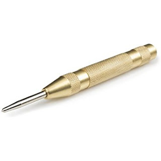
(10) CENTER PUNCH
  The center punch is used to mark light points on scribed lines which are the limits of a surface or edge.

CENTER PUNCH
CENTER PUNCH


READ MORE: TOP 7 PRECAUTIONS TO TAKE WHILE USING THE MARKING OUT TOOLS

PLEASE DON'T FORGET TO SHARE, COMMENT, FOLLOW US, LIKE MY FACEBOOK PAGE, AND SUBSCRIBE TO GET THE LATEST UPDATES..